PHYSICS BOOK CLASS(10th)

3. Electricity
Electric Circuit
The electric circuits are closed-loop or path which forms a network of electrical components, where electrons are able to flow. This path is made using electrical wires and is powered by a source, like a battery. The start of the point from where the electrons start flowing is called the source whereas the point where electrons leave the electrical circuit is called the return. Let’s conduct a small experiment, you would need the following,
- Electric bulb
- Wire
- Electrical tape
- A battery
Connect the wires to the bulb and connect one end of the wire to the battery, notice what happens, there won’t be any change in the bulb, but when you connect the free wire to the battery and complete the circuit, you will notice that the bulb starts glowing, therefore the circuit must be completed in order for the current to flow.
An electrical circuit complete only when there is at least one closed loop from positive to the negative end. This is the simplest form of an electric circuit, the circuit found inside a television is more complicated and has different components.

You might have seen these danger signs on electric poles, transformers and sometimes even on some electrical equipment at home, it is to warn you about the dangers of electricity, and electricity, if not handled properly, could be lethal and can even cause deaths. Electric wires sockets and live wire should be properly insulated and kept away from the reach of children, the voltage in a small battery does not exceed more than 12 volts but the voltage in a transformer may reach up to 11000 volts.
Faulty electrical circuits because fire, for fires caused due to electrical failure use of water to extinguish must be avoided, there are special extinguishers for the same.
We have come to a conclusion that electric current flows only when there is a complete uninterrupted connection from a battery through different components back to the battery, any interruption will stop the flow of current
Electric batteries should also be handled carefully, never connect two terminals of the battery without a bulb or a load, because the chemicals inside the battery react so quickly that they generate an immense amount of energy, which can even cause them to burst.
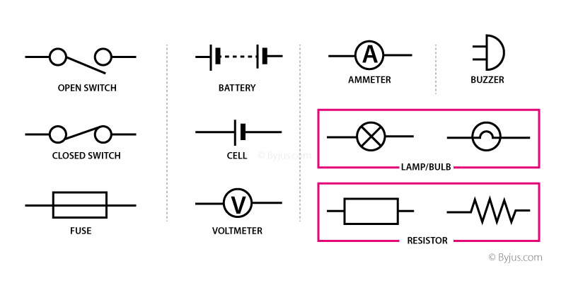
Electric Circuit Symbols
Every component and product of the electric circuit contains a symbol. The symbols represent parts of the circuit in a circuit diagram. Beneath are the basic set of symbols that are present in a circuit diagram.

Simple Circuit
A simple circuit comprises the power source, conductors, switch, and load.
- Cell: It is the power source.
- Load: It is also termed as the resistor. It is a light bulb that lights when the circuit is turned on.
- Conductors: They are made of copper wires with no insulation. One end of the wire is connected the load to the power source and the other end of the wire connects the power source back to the load.
- Switch: It is a small gap in the circuit. There are various types of switches. A switch can be used to open or close a circuit.
Electric Circuit Formula
Following are the list of formulas that are used in electric circuits are:
| Quantity | Formula | Notations |
| Electric current |
| |
| Resistance |
| |
| Voltage |
| |
| Power |
| |
| Series circuit |
| |
| Parallel circuit |
|